


Please Leave Us A Message
Privacy statement: Your privacy is very important to Us. Our company promises not to disclose your personal information to any external company with out your explicit permission.
 October 20, 2021
Foreword
With the rapid development of the domestic machine tool industry, everyone has higher and higher requirements for the use load, speed, and precision life of the screw. Therefore, for screw designers, the load problem of the screw, thermal deformation, and positioning accuracy There must be a clear understanding of the problem of service life and so on.
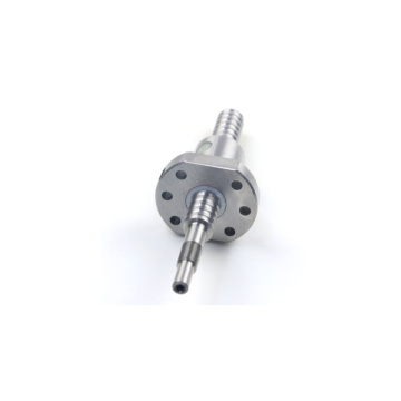
1. Specific requirements for screw load of HDL50 CMM
In October 2007, Dalian Machine Tool Group's machining center developed its own HDL50 three-axis machining unit, which has stringent technical requirements for the screw, requiring its rapid movement speed v = 54m/min, acceleration is a = 0.5g, dynamic load , C = 58200N, static load 158000N, pitch P = 20mm (determined by FANUC servo motor a30/3000i), stroke ST = 800mm, using one end fixed to the other end to support the installation. Its structure is shown in Figure 1:

1, tighten the nut 2, flange 3, Bearing
4, carrying heavy objects 5, end caps 6, motor bearings
7, bearing seat 8, bearing cover 9, screw 10, screw nut
11. Flange 12, Bearing 13, Coupling 14, Motor Figure 1
1.1 Calculation of axial load 1.1.1 (horizontal reciprocating motion)

figure 2
The horizontal reciprocating movement of the nut and bearing weight, as shown in Fig. 2, the axial load analysis is as follows:
Equi-acceleration to the left: Fa1=μ×mg+f+ma
Constant speed to the left: Fa2=μ×mg+f
Deceleration to the left, etc.: Fa3=μ×mg+f-ma
Accelerating movement to the right: Fa4=-μ×mg-f-ma
Constant speed to the right: Fa5=-μ×mg-f
Deceleration to the right, etc.: Fa6=-μ×mg-f+ma
a=Vmax/T
Vmax: the highest speed
T: time taken to reach the maximum speed
m: total mass, which refers to the weight of all the nuts driven by the nut μ: rail friction coefficient
f: The resistance at no load can therefore be the maximum nut load when accelerating to the left or accelerating to the right, so it is important to refer to this value when designing the axial load.
Fa1=μ×mg+f+ma=0.01×2150×9.8+100+2150×0.5×9.8
=10845.7N

1.1.2 (vertical reciprocating motion), as shown in Fig. 3, its axial load is analyzed as follows:
Accelerating motion such as rising: Fa1=μ×mg+f+m(a+g)
Ascending isometric exercise: Fa2=μ×mg+f+mg
Ascending isometric motion: Fa3=μ×mg+f+m(ga)
Falling and other accelerated motion: Fa4=m(ga)-μ×mg-f
Decreasing constant velocity exercise: Fa5=mg-μ×mg-f
Decrease and other deceleration movements: Fa6=m(g+a)- μ×mg-f
This results in the maximum load on the nut during acceleration and other acceleration movements. Therefore, it is important to refer to this value when designing the axial load.
Fa1=μ×mg+f+m(a+g)= 0.0l×328×9.8+100+328×1.5×9.8
=4953N
1.2 Screw shaft allow axial load Due to the self-weight of the table, spindle box, workpiece, etc., the compression load on the screw itself must be checked for the safety of screw setback. The following formula analysis:
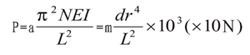
a: safety factor (take a=0.5) E: elastic coefficient
I: diameter of screw shaft bottom (I=πdr4/640N/MM2)
Dr: screw shaft base diameter (dr = screw pitch diameter - steel ball diameter mm)
L: Installation clearance (relative distance between two ends of the screw)
m, N: Factor support depending on how the screw is installed - Support m=5.1 (N=1)
Fixed-support m=10.2 (N=2)
Fixed-fixed m=20.3 (N=4)
Fixed-free m=1.3 (N=1/4)

1.3 Basic Static Load Rating Co
That is, the axially-stationary load of the screw is the sum of the amount of permanent deformation of the screw and the permanent deformation of the steel ball itself when the screw receives the permanent deformation between the contact between the screw groove and the ball (ie, the nut and the screw shaft) and reaches 0.01% of the ball diameter. The maximum axial force, this load is the basic static load rating.
1.4 Basic Dynamic Load Rating Ca
Dynamic load refers to a batch of screws of the same specification that are rotated 10 times under the same conditions, and 90% of the leadscrew will not be stripped due to fatigue. This axial load is the dynamic rated load.
2, HDL50 coordinate processing unit screw positioning accuracy
In the error of the feed accuracy of the machine tool, the lead precision and the rigidity of the feed system are the focus of the study. Other factors such as the thermal deformation caused by temperature rise and the assembly accuracy of the guide surface must also be considered.
2.1 Solution to Hot Screw Deformation The screw shaft deforms due to heat and causes a change in positioning accuracy. The amount of heat distortion can be calculated by the following formula:

The above formula can be interpreted as a Lead Screw of 1000mm in length will produce 12μm elongation. Therefore, even if the lead of the screw shaft is processed with high accuracy, the high-precision positioning requirements cannot be satisfied due to the deformation caused by the temperature rise. In addition, the higher the operating speed of the screw, the average temperature rise is also relatively higher, the greater the thermal deformation. Therefore, we must come up with a solution to this problem. There are three solutions to this problem:
(1) Control the amount of heat:
a: Select the appropriate pre-pressure.
b: Select the correct and appropriate amount of lubricant.
c: Increase the lead of the Ball Screw and reduce the number of revolutions.
(2) Applying Forced Cooling a: Using a hollow lead screw, use the cooling fluid to pass in and take away the generated heat.
b: The outer edge of the screw shaft is cooled with lubricating oil or air.
(3) Avoid the effect of temperature rise:
a: Calculate the target value of the cumulative lead error by taking a negative value correction.
b: Wait until the high temperature of the standby bed rises before use.
c: Apply pretension when the screw is installed.
d: Use grating ruler for error compensation; use closed-loop control system.
2.2 Specific calculation of HDLSO screw thermal deformation According to the bearing load capacity, the cumulative lead target temperature rise 3 °C

3, the life of the screw
When the screw is used normally, it will be unusable due to various reasons after a period of time. This time is its life. It is generally divided into two types:
a. Fatigue life: When peeling occurs. b. Accuracy life: When accuracy deteriorates due to wear.
3.1 Lifetime Calculations Fatigue life has three expressions:
a: total revolution number b: total operation time c: total stroke
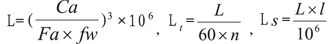
The long life will make the size of the selected screw too large, resulting in uneconomical results, so most will choose from 10,000 hours to 20,000 hours.
4 Conclusion:
This article gives a brief example of some of the most basic elements that a ball screw should pay attention to when it comes to designing a machine tool. Other designers can also refer to the calculations used in this article for design; as far as our domestic screw production technology and abroad have so far There is a big gap. Therefore, for our designers, we should learn advanced foreign technologies and methods, absorb and digest them, and introduce the technology into China to make up for the lack of certain domestic technologies.
The above is the Talking about the Selection of Ball Screw in Machine Tool Design we have listed for you. You can submit the following form to obtain more industry information we provide for you.
You can visit our website or contact us, and we will provide the latest consultation and solutions
Send Inquiry
Most Popular
lastest New
Related Products
Send Inquiry
Privacy statement: Your privacy is very important to Us. Our company promises not to disclose your personal information to any external company with out your explicit permission.
Fill in more information so that we can get in touch with you faster
Privacy statement: Your privacy is very important to Us. Our company promises not to disclose your personal information to any external company with out your explicit permission.